


The media could not be loaded.
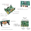
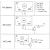
Regardless of the input voltage, the HC-SR501 output trigger voltage is only 3.3V-3.4V DC. This means I can only use 5V DC opto-relays, instead of 12V opto-relays as their trigger voltage is >4.5V DC. This required making a 5V circuit to power the HC-SR501 and the relays. The video shows the DC-DC Buck converters (blue LEDs) and the 5V DC opto-relays (red LEDs) driving the HC-SR501, one motor, and the flame bulb. The simplified schematic shows the wiring layout I made with applied voltages.
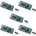
The second issue to note with the HC-SR501 is the delay pot. It only takes a 10 degree turn of the pot to go from the minimum delay time of one second to 25 seconds.
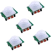
Their sensitivity is very good. I have yet to try adding a thermistor to the HC-SR501 to test its night time capabilities.
FYI: I'm using the B0CMXCZX9Y nylon standoffs (via Amazon) to mount all of these boards.
UPDATE: I'm holding back from installing a thermistor. Low light sensitivity is excellent.

